When I started working as a low voltage instrument current transformer (CT) supplier over a decade ago, one of the most common questions I heard from our customers – electricians, system integrators, and industrial maintenance teams alike – wasn’t about how to order a CT or what size they needed. It was: “What exactly is CT burden, and how do I calculate it correctly?” I remember a project last year where a local manufacturing plant installed three new low voltage CTs for their production line, only to have the current readings jump wildly within a week. Turned out, they’d miscalculated their burden, and the CTs couldn’t handle the extra load on their secondary side. That mistake cost them two days of downtime and a lot of frustration – and it’s exactly why I’m breaking down CT burden calculation today, straight from the field, no overly technical jargon, just what you need to get it right. Low Voltage Instrument Current Transformer
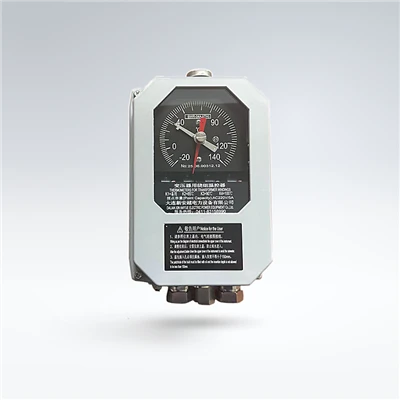
First, let’s get clear on what CT burden actually is. Put simply, a current transformer works like a energy converter: it steps down the high current flowing through your primary conductor (the wire you’re measuring) to a safe, low level – usually 1A or 5A on the secondary side – that can be read by meters, relays, or monitoring devices. Burden is the total electrical load on that secondary circuit. Every component wired to the CT’s secondary – the meter itself, the connecting wires, terminal blocks, even test switches if you have them – adds to this burden. Too little burden? Well, that’s rare for low voltage CTs, but it can cause the secondary voltage to spike, damaging connected equipment. Too much burden, though, is the real villain here. It makes the CT’s current readings inaccurate, sometimes off by 5% or more (which is a huge deal for billing or load monitoring), and can even overheat the CT’s secondary winding over time. That’s the problem the plant I mentioned ran into: they added an extra amp meter to their setup but forgot to account for the new device’s burden, so their existing CTs were overloaded.
Now, the first rule of calculating CT burden is that you have to use the same unit every time. Most of our customers are used to seeing burden listed in either ohms (Ω) or volt-amperes (VA), and you need to be able to switch between them easily. VA is a unit of apparent power, which is more common for CT manufacturers to specify, while ohms are what you’ll use to add up the resistance of wires and components. The good news is the conversion is straightforward: VA = I² × R, where I is the rated secondary current of your CT (either 1A or 5A). That means if your CT is rated for 5A, you take each component’s VA, divide by 25 (since 5 squared is 25) to get its ohm value. If it’s rated for 1A, divide by 1 (since 1 squared is 1) – simple as that. I always keep a cheat sheet for this, because it’s easy to mix up the numbers when you’re in the middle of a rush order.
Next, break down the burden into three parts: components connected to the secondary, connecting wires, and any other accessories. Let’s start with the connected devices – this is where most people start, but also where they cut corners. Every device that gets current from the CT’s secondary has a published burden value. For example, a standard digital amp meter might list its burden as 0.1 VA at 5A, while an overcurrent relay could be 0.2 VA. If you’re wiring multiple devices in parallel (which is what you do with CT secondaries, since they all need the same current reading), you add their VA values together. Wait, hold on – important note here: CT secondaries are wired in parallel, not series, so their burdens add, not their currents. I’ve seen so many people mix that up and end up with way higher burden than they expected. That parallel wiring is non-negotiable, by the way; never series two CT secondaries, that’s a safety hazard and ruins readings.
Then there’s the connecting wires – this is the part that’s often overlooked, and it can make a big difference, especially if you’re running wires a long distance. Let’s say you have a CT installed in a switchgear room, and you need to run the secondary wire 50 feet to your monitoring panel. The resistance of copper wire is roughly 0.00064 ohms per foot for 14 AWG wire (the most common size for low voltage CT secondaries). So two wires (you have a secondary “hot” and a secondary “common,” right? It’s a loop) run 50 feet each, that’s 100 feet total. 100 feet × 0.00064 Ω/ft = 0.064 Ω. Now convert that to VA for a 5A CT: 0.064 × 25 = 1.6 VA. That’s not huge, but if you’re running 100 feet of 12 AWG wire, it drops to 0.08 Ω, or 2 VA – still a number you have to add to your total. A lot of customers will use whatever scrap wire they have on hand, but that’s a mistake. If you’re going longer than 50 feet, upsizing your wire to 12 or even 10 AWG can save you from eating up extra burden. I always advise customers to measure the exact length of their secondary run, not just guess, because that’s where errors creep in.
The third part is accessories: terminal blocks, test switches, fuse holders, anything else between the CT and the devices. A standard terminal block is usually around 0.05 Ω per connection, and if you have four or five connections, that adds up to some extra resistance. Test switches, which are used to disconnect a meter for maintenance without turning off the CT, typically add 0.1 to 0.2 Ω of burden. It’s easy to skip these numbers, but when you add all three parts together – devices, wires, accessories – that’s your total secondary burden.
Wait a second – how do you know what the CT’s maximum rated burden is? That’s the other half of the equation. Every low voltage CT we manufacture has a nameplate that lists its rated burden, usually in VA. For example, a common 5A CT we make is rated for 5 VA, meaning its maximum allowable secondary burden is 5 VA. So your total calculated burden has to be less than or equal to that rated burden – with a little buffer, actually. I always recommend leaving 10-15% headroom, just in case you add a device later or the wire length ends up being a little longer than planned. The plant I worked with earlier calculated only the burden of their two meters, forgot the wire run and the new terminal block, and came in at 5.8 VA for a 5 VA CT – that’s why the readings were off. Small mistake, big problem.
Let’s walk through a real example, so this isn’t just theory. Say you have a 5A CT, rated for 5 VA. Your setup is: two digital amp meters (0.1 VA each, so 0.2 VA total), a test switch (0.2 VA), and secondary wires that run 70 feet from the CT to the panel. Let’s calculate each part:
- Connected devices: 0.1 + 0.1 + 0.2 = 0.4 VA.
- Wires: 70 feet each way, so 140 feet total. Using 14 AWG, that’s 140 × 0.00064 = 0.0896 Ω. Convert to VA: 0.0896 × 25 = 2.24 VA.
- Accessories: Terminal block adds 0.05 VA, so total accessories 0.05 VA.
Add all together: 0.4 + 2.24 + 0.05 = 2.69 VA. That’s well under the 5 VA rated burden, plus we have 2.31 VA of headroom – perfect, this setup will work. If you’d used 12 AWG wire, that would drop to 1.4 VA, even more headroom. If you’d used a 1A CT, same example would be 1.076 Ω, so (1.076) × 1 = 1.076 VA, still way under.
Now, a few common pitfalls I see every day, especially with new customers. First, mixing up primary and secondary currents. Burden is only on the secondary side, never the primary. The primary current is what you’re measuring, so you don’t calculate burden from that. Second, forgetting that parallel wiring adds burdens, not currents. I had a customer last month who wired three devices in series for some reason, thinking the currents would add, and ended up with a reading 20% lower than actual. That’s a safety risk, too – CT secondaries must always be parallel, and never open-circuited when energized, but that’s a topic for another day. Third, using the wrong conversion between ohms and VA. If your CT is 5A, squaring 5 gives 25, not 5 – I’ve seen people divide by 5 and end up with a burden that’s way higher than it actually is. Fourth, not accounting for wire length when the run is over 50 feet. Every foot adds resistance, and those add up fast.
Another thing to remember: CT burden depends on the accuracy class you need. If you’re using a CT for billing purposes (which requires high accuracy, like 0.5% or better), you need to make sure your burden is as close to the CT’s rated burden as possible, and definitely not over. The accuracy of a CT is specified at its rated burden, so if you run below that burden, you might get slightly better accuracy, but if you go over, your accuracy drops. If you’re using a CT for basic overload protection or status monitoring (accuracy class 1% or even 2%), you have a little more leeway, but it’s still not worth cutting corners.
Wait, what if you need to add more devices later? Plan ahead when you first spec your CT. If you know you’ll need to add a third meter in the future, don’t get a 5 VA CT – go for a 10 VA model, so you have extra space. That’s what I always advise customers: specify the maximum number of devices you might need, calculate their total burden upfront, then add 20% to that, and that’s the minimum rated burden you need for your CT. It’s way cheaper to get a slightly higher rated CT upfront than to replace it a year later when you add a new monitoring device.
From a supplier’s perspective, this is why we include a full burden calculation guide with every low voltage CT we ship, and we’re always available to walk a customer through it if they’re unsure. Last quarter, a small electrical contractor called us panicking because they had a job that required CTs for 12 motors, and they didn’t want to miscalculate and cause downtime. We sent them the cheat sheet, walked them through their exact setup, and helped them pick CTs with the right rated burden. They ended up ordering 18 CTs that week, and their job went off without a hitch. That’s the kind of service that matters – not just selling a product, but making sure it works for their application.
So to wrap this up, the steps to calculate CT burden are simple, if you take it one part at a time: first, note your CT’s rated secondary current (1A or 5A) and rated burden (in VA). Second, add up the VA of all secondary devices you’re connecting. Third, calculate the VA of your connecting wires by measuring their total length, finding their resistance, then converting to VA using I² × R (remember to square 1 or 5, depending on your CT). Fourth, add in VA from any accessories like terminals or test switches. Fifth, add all those numbers together, and make sure the total is less than the CT’s rated burden – leave a little headroom for future changes.
If you’re not sure about your calculation, or you need help picking the right low voltage CT for your project, don’t guess. Reach out to our team. We’ve been working with industrial facilities, commercial buildings, and electrical contractors for years, and we’ve helped hundreds of customers get their burden calculations right the first time. There’s no shame in asking for help – the alternative is downtime, inaccurate readings, and unnecessary costs, which no one wants.
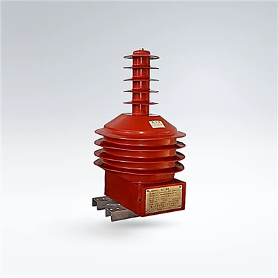
I always say that a CT is only as good as the setup around it. Calculating burden correctly isn’t rocket science, but it’s a critical step that makes all the difference between a reliable monitoring system and one that causes problems. After that plant incident two years ago, we started including a quick burden check on every order we fulfill, just to make sure our customers are on the right track. It’s just part of being a good supplier, not just selling product, but supporting our customers every step of the way.
MV Instrument Voltage Transformer References
- International Electrotechnical Commission. (2018). IEC 60044-1: Instrument transformers – Part 1: Current transformers.
- Miller, J. (2020). Practical Current Transformer Applications for Low Voltage Systems. Electrical Contractor Magazine.
- Siemens Energy. (2021). Low Voltage Instrument Transformer Application Guide.
Dalian Xin’anyue Electric Power Equipment Co., Ltd.
Dalian Xin’anyue Electric Power Equipment Co., Ltd. is one of the most reliable low voltage instrument current transformer manufacturers and suppliers in China, featured by quality products and good price. Please rest assured to wholesale durable low voltage instrument current transformer in stock here from our factory. We also accept customized orders.
Address: No.99, Group 1, Chongwangmiao Community, Taiping Street, Pulandian District, Dalian City, Liaoning Province, China
E-mail: sales@dlxay.com
WebSite: https://www.xayelectric.com/
